Manufacture of forming tools with subcutaneous cooling circuits by means of laser cladding
In the manufacturing processes of transformation of metallic, plastic, and ceramic materials, many of the relevant events occur in areas of difficult access in which, due to working conditions, it is not possible to capture the data directly. As a consequence, currently, the monitoring of these processes is carried out through data taken indirectly; the same happens with the modeling and simulation tools that feed on these parameters. Being capable to advance in the integration of transducers that allow capturing this data of great relevance is a fundamental aspect to improve its control and efficiency.
A particularly representative case of this problem is found in forming tools that work in adverse conditions (high temperatures and wear). In these cases, the main challenge is to be able to ensure the implementation of commercial sensors on tool surfaces guaranteeing their integrity, as well as the conduction of power and the reading of their signals by standard wiring. Therefore, to address the technological challenges posed by this objective, in the first place, the thermal problems associated with this integration must be solved.
In the case of the design of forming tools with cooling channels, necessary to optimize the manufacturing cycles in those parts whose cooling is a fundamental part of the process to ensure their quality, combinations of different materials with complementary properties are usually used: a core with a high thermal conductivity, a surface with high wear resistance and corrosion-resistant cooling circuits. While it is difficult to combine these properties using conventional technologies, laser cladding offers new manufacturing opportunities. Likewise, additive technologies make it possible to overcome challenges associated with the shape of the cooling channels, allowing to create conformal cooling channels, overcoming the straight lines of conventional channels, which provide a more uniform cooling, shorten the cooling cycle of the component and contribute to reduce rejection rates.
However, the laser cladding process also raises unknowns and gaps that experimental research must progressively solve. These include the potential impact that the addition of metal through heat can have on the elements to be integrated and the definition of the optimal settings to work safely.
In order to exploit the opportunities offered by laser cladding technology to integrate wiring on the surface of forming tools, the technology centers Azterlan and Tekniker, members of BRTA, within the framework of the SUSIE* project (file number KK-2020/00054), have developed a process to add powder metal by laser cladding. This process is oriented to the manufacture of cooling channels, optimizing the most relevant process parameters, such as laser power, feed speed or dust flow, and establishing the most appropriate supply strategies to seal these cooling channels without deforming or piercing the auxiliary elements, in order to guarantee their tightness and avoid leakage of refrigerant fluid.
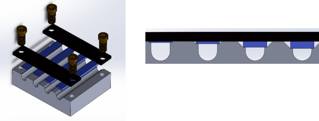 Image 1. Manufacturing scheme of the sample that simulates a die (gray), manufactured in 1.2311, with cooling channels on which they will be welded by laser cladding caps (blue) of AISI 316L as the construction material of the cooling channels.
After a series of experimental tests that allow to evaluate the behavior of the samples to the contribution of 1.2344 steel by means of laser cladding technology, it is concluded that the most viable working method is through 3 consecutive stages that allow:
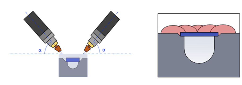 Image 2. Left; Stage 1: Closing of edges. Right; Stage 2: Creation of the mattress layer.
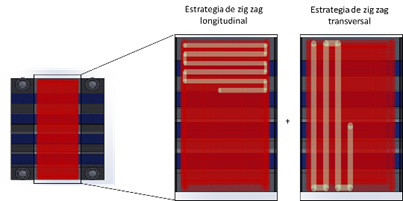 Image 3. EStage 3, massive surface coating.
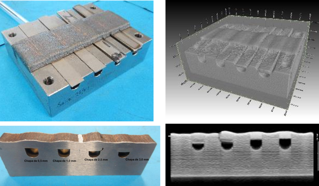 Image 4. Top left: cooling channels created on a die sample. Top right: tomographic analysis of the sample. Bottom left: section of the selected area of the sample by tomography. Bottom right: The plane most susceptible to developing poor performance, detected by X-Ray Tomography.
Externally, no significant cracks, pores or defects have been observed, although there is variability in terms of dimensionality when it comes to the height of the recharge, as well as thermal deformation in part of the stainless-steel sheets. Both aspects can also be seen in the general tomography of the specimen (Image 4, sup. right). The analysis on the 3D solid provided by the tomography shows a high internal health. The study plane most susceptible to developing poor sample performance (Image 4, inf. right) has been selected for metallographic analysis and hardness control. Aspects such as porosity, adhesion, deformations, or the thermal affectation produced by the process in the AISI 316L sheets on which 1.2344 tool steel has been added have been analyzed. In all cases, the study of the integrity of the joints (Image 5) has offered satisfactory results.
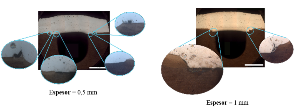 Imagen 5. Analysis of the integrity of the cooling channels.
Based on the results obtained, it has been demonstrated that it is feasible to manufacture cooling channels with flat 316L caps on a base of a 1.2311 alloy with semi-cylindrical lower cooling surface circuits using laser cladding technology.
*Recognition: This study has been developed within the SUSIE project (file number KK-2020/00054) aimed at the disruptive integration of intelligent sensors in machines, through the use of additive manufacturing technologies. This project is funded by the Elkartek programme of the Basque Government.
Study of manufacture of cooling circuits on a tool steel
The selection of the materials to carry out this study is carried so they meet the requirements of thermal conductivity and chemical compatibility with the materials of contribution and substrate (tool). The tool steel selected for the die base is plastic mold steel 1.2311. It is a steel with good machinability and high thermal conductivity. After machining a sample that serves as the base of the die, seats are machined on it to accommodate the plates made of 316L steel of different thickness with the aim of exploring the survival rate of the ducts depending on the thickness of the covers. The test geometries contemplate a semi-cylindrical lower cooling surface of the same diameter in all cases. For the construction of the sub-cutaneous cooling channels, AISI 316L austenitic stainless steel with high corrosion resistance has been selected. For this purpose, 316L sheets of different thickness are selected, which serve as covers of the semicircular ducts machined at the base of the die. After selection, sheets of different thicknesses are manufactured that are used as a flat specimen or substrate, where the first supply tests are carried out, with the aim of establishing the minimum thickness that allows, on the one hand, to guarantee the integrity of the sheet after the contribution, and, on the other, to minimize the distortions of the sheet, which could impair the final sealing of the cooling channels. Finally, the material selected to be added in powder state is the hot working 1.2344 tool steel Image 1. Manufacturing scheme of the sample that simulates a die (gray), manufactured in 1.2311, with cooling channels on which they will be welded by laser cladding caps (blue) of AISI 316L as the construction material of the cooling channels.
After a series of experimental tests that allow to evaluate the behavior of the samples to the contribution of 1.2344 steel by means of laser cladding technology, it is concluded that the most viable working method is through 3 consecutive stages that allow:
- Generation of the sealing closures on the edges of the sheets/caps (Image 2, left): This first stage is carried out with a power of 1.5 kW, a speed of 20 mm/s, with a dust flow rate of 10 g/min and an angle for the nozzle of 75º.
- Generation of a mattress that prevents the perforation of the sheets (Image 2, right): In this second stage a power of 0.8 kW is used, a speed of 20 mm / s, a dust flow of 1.2344 of 10 g / min, an overlap of 1mm, a total of 3 layers.
- Massive surface recharge (Image 3): In the third stage, a power of 1.2 kW, a speed of 15 mm/s, a dust flow rate of 10 g/min, an overlap of 1 mm and a total of 6 layers are used. The change of direction between layers has been made in zig-zag.
 Image 2. Left; Stage 1: Closing of edges. Right; Stage 2: Creation of the mattress layer.
 Image 3. EStage 3, massive surface coating.
Analysis of the results and conclusions
Subsequent analyses carried out on the samples developed have demonstrated the viability of laser cladding as a means for manufacturing cooling channels on forming manufacturing tool surfaces. Image 4. Top left: cooling channels created on a die sample. Top right: tomographic analysis of the sample. Bottom left: section of the selected area of the sample by tomography. Bottom right: The plane most susceptible to developing poor performance, detected by X-Ray Tomography.
Externally, no significant cracks, pores or defects have been observed, although there is variability in terms of dimensionality when it comes to the height of the recharge, as well as thermal deformation in part of the stainless-steel sheets. Both aspects can also be seen in the general tomography of the specimen (Image 4, sup. right). The analysis on the 3D solid provided by the tomography shows a high internal health. The study plane most susceptible to developing poor sample performance (Image 4, inf. right) has been selected for metallographic analysis and hardness control. Aspects such as porosity, adhesion, deformations, or the thermal affectation produced by the process in the AISI 316L sheets on which 1.2344 tool steel has been added have been analyzed. In all cases, the study of the integrity of the joints (Image 5) has offered satisfactory results.
 Imagen 5. Analysis of the integrity of the cooling channels.
Based on the results obtained, it has been demonstrated that it is feasible to manufacture cooling channels with flat 316L caps on a base of a 1.2311 alloy with semi-cylindrical lower cooling surface circuits using laser cladding technology.
*Recognition: This study has been developed within the SUSIE project (file number KK-2020/00054) aimed at the disruptive integration of intelligent sensors in machines, through the use of additive manufacturing technologies. This project is funded by the Elkartek programme of the Basque Government.

